Project - ArtNet to Pixel Driver
The pandemic lockdown this year has given me an opportunity to work on a few projects that had been on the back burner for a while, and this ArtNet Pixel driver was one of the first. The aim was to produce addressable LED panels from stuff that was lying around in the workshop that I could use in future dance or music events and DJ jobs, and make them work with industry standard software such as QLC+ or MadMapper.
I like repurposing things to do other things, so rather than build a panel from scratch with new materials I started with what I had. The base board for the LED matrix was built around an unused Ikea shelf, and the protective covers for the pixels themselves are trimmed-down packaging domes for daily contact lenses! Obviously you can use whatever you have lying around but the challenge is to be as creative as possible.
Please note that in order to fit into an Arduino Uno (I had a few spare) the driver software is very cut-down and may not be suitable for many installations: it only implements broadcast mode and does not respond to ArtNet polls or mode changes; the IP address and mask are set at time of programming, so you have to plan ahead if you are expecting to use this alongside other ArtNet equipment; and there are no doubt other restrictions that I haven't thought of yet. Use this at your own risk, and only attempt to build it if you know what the hell you are doing with electrical stuff. In other words, any damage or loss to anything - including yourself - that may come about by building this is entirely your problem and not the responsibility of The Lacuna Works or anyone associated with The Lacuna Works. If you're happy with that then here are some of the details of what I did.
Components used:
- Arduino Uno R3
- Funduino W5811 Ethernet Board
- 25 x Ws2811 5v 3-wire Neopixels
Additional components included a PSU board salvaged from an old DVD player, various connectors and sockets, and a lot of thin flexible wire.
LED Matrix Panels
Panel Construction
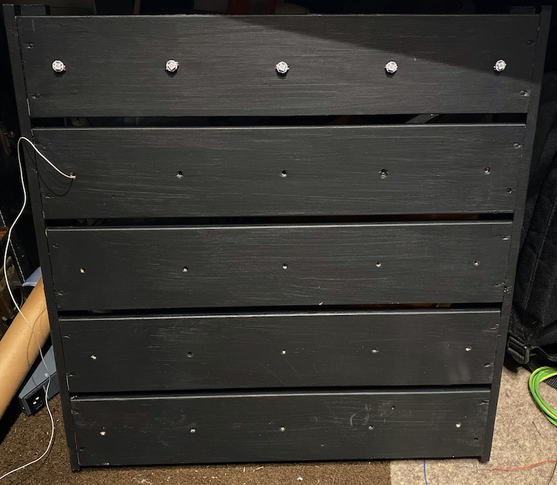
Take one Ikea shelf, a large piece of board, or whatever you are going to use as the backboard and drill holes for each of the pixels. The pixels can be in any pattern you like, but check with whatever software you are going to be using to control the matrix when it is complete to see how it works with non-grid patterns. Make sure you paint it before wiring in any of the pixels as it will be impossible to get it to look neat later.
Assuming you are going for a square grid, pick one corner as the start and begin soldering pixels onto wire, ensuring that whatever shape you design you connect them in the correct direction, with Data Out from one going to Data In of the next.
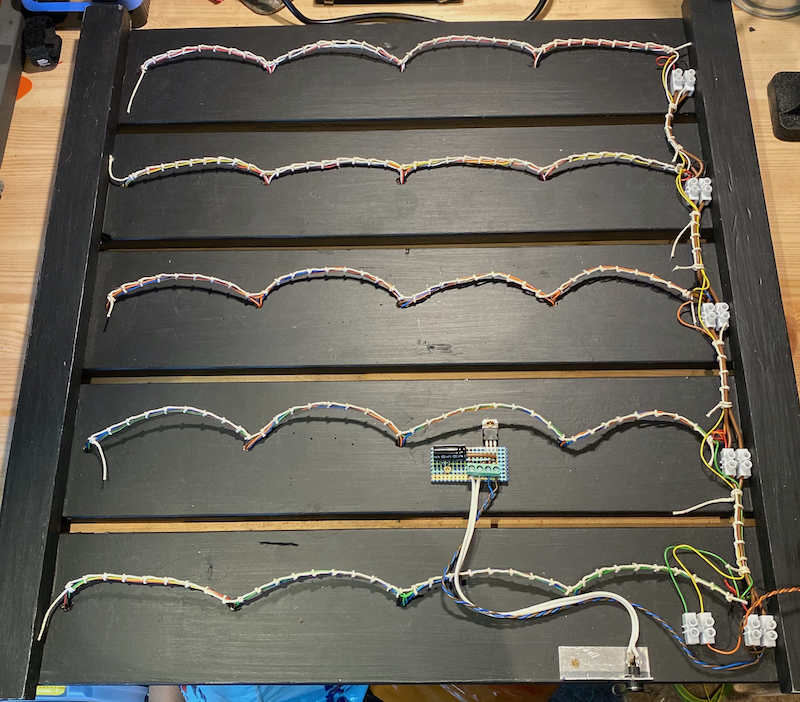
Most software seems to expect panels to be wired in zig-zag layout, so when you finish the first row run a wire from the Data Out of the last pixel back to the Data In of the pixel at the start of the next row and continue in the same direction. This will result in the pixels being numbered:
                            00 - 01 - 02 - 03 - 04

                                05 - 06 - 07 - 08 - 09

                                10 - 11 - 12 - 13 - 14

                                15 - 16 - 17 - 18 - 19

                                20 - 21 - 22 - 23 - 24
... and can be addressed as such in whatever controlling software you are using. If you are linking more than one board together by daisy-chaining the Data Out from one to the Data In of the next then the second board will be addressed as:
                            25 - 26 - 27 - 28 - 29

                                30 - 31 - 32 - 33 - 34
and so on. As each pixel has three channels - R G B - the actual DMX channel address for each pixel will be multiplied by 3.
Wiring
Keep the wiring neat, ideally lacing the looms together and anchoring them at regular intervals as this will help to avoid vibration damage in use.
I added a small voltage regulator board to the panel as I knew that in practice I would be feeding this with all sorts of random voltages and the pixels require a constant 5v. I used a 7805 regulator because I had a few of them lying around, but you can use anything you like. If you know you are going to power the boards with the correct voltage you probably won't need it.
Pixel Protection
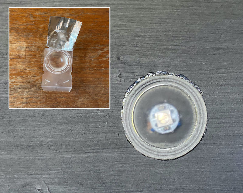
I stuck the pixels onto the board using silicone bath sealant, then glued trimmed-down contact lens pots over the top of each one to protect them and act as small diffusers. You can use anything for this, including a single sheet of perspex across the whole panel, but I like the idea of being able to reuse something that I habitually throw away in quantity, hence the contact lens shipping pots.
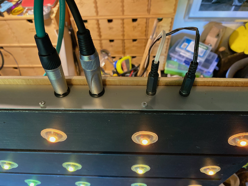
Connections
Power in and out are by standard DC co-axial connectors so I can feed more than one panel from a single PSU lump if that's easiest. The two jack connections are PixData In (right) and PixData Out (left) so I can daisy-chain multiple panels together.
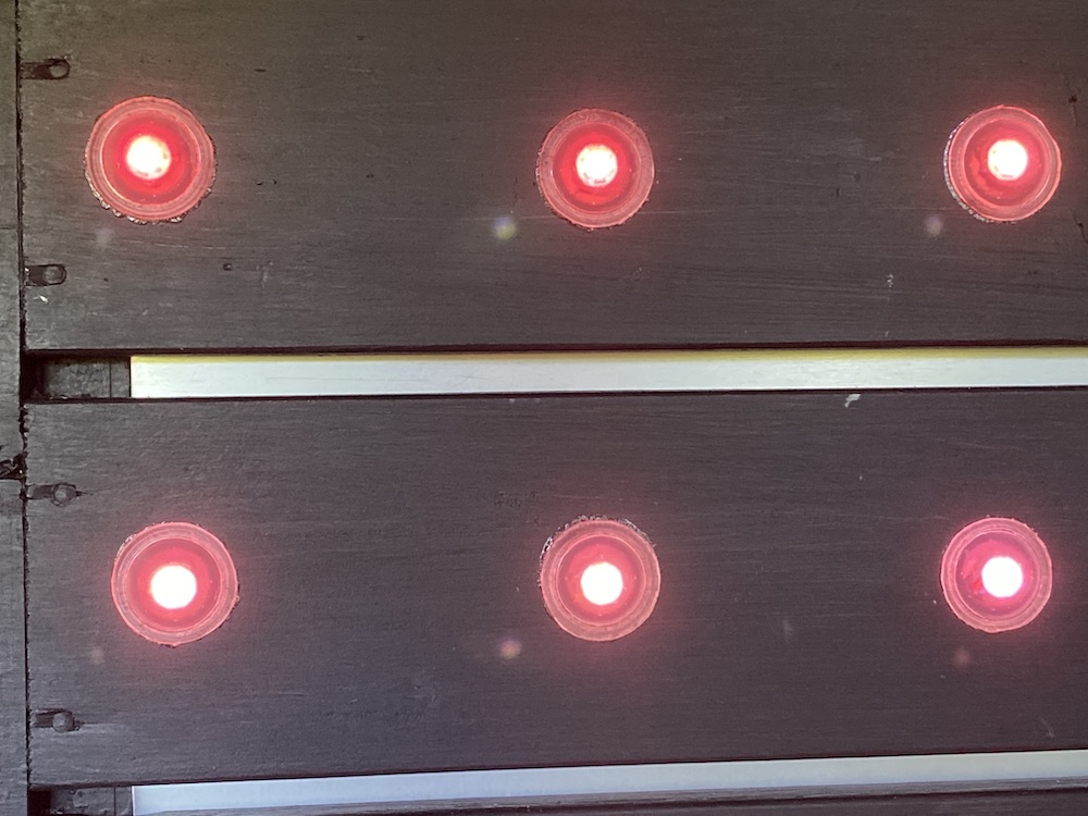
The video at the top of this page shows two panels controlled from QLC+ running on a Mac elsewhere on the network. QLC+ has no facility for mapping patterns across multiple Pixel or RGB matrices so they operate independently here, but that is a limitation of the controlling software not the panels, so if I use MadMapper to control them they can be linked and patterns displayed across both together.
Matrix Controller
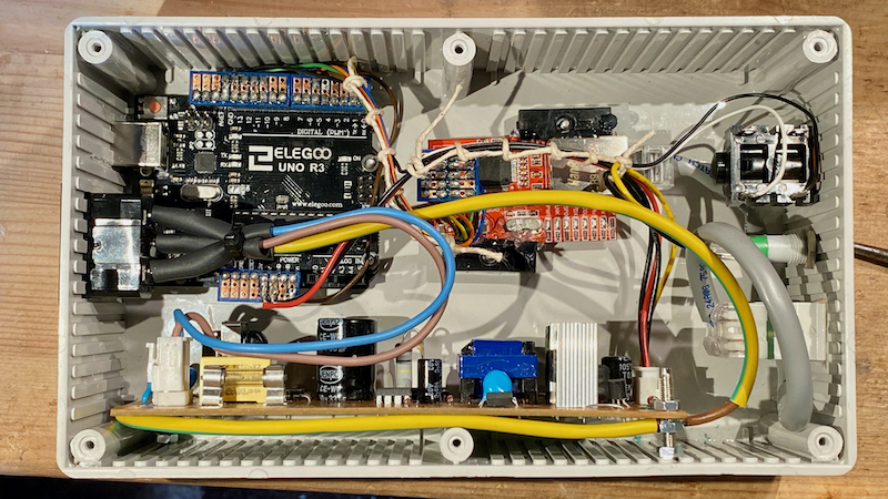
Design and layout is entirely up to you, but the components and connections that I used are as follows:
- Arduino Uno board
- Funduino W5811 or equivalent ethernet board
The Uno is connected to the Ethernet board using SPI, so the following pins need to be linked:
- Uno Pin 10 (CS) -> Funduino NSS
- Uno Pin 11 (MOSI) -> Funduino MO
- Uno Pin 12 (MISO) -> Funduino MI
- Uno Pin 13 (SCK) - Funduino SCK
Also link the 5v and Gnd pins of the Funduino to the 5v and Gnd pins of the Uno.
Note: You can use any Ethernet board, but the code may need to be adjusted to suit.
The connections to the pixel panel Data In port is from Pin 5 of the Uno. This can be changed in the code if needed.
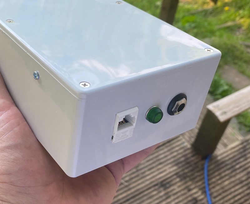
Build the whole project into a box with a suitable power supply and you are good to go. I used a standard T-S 1/4" jack for the pixel data feed, but you may wish to use something less likely to be confused with audio, or something that could carry power as well if your controller has a suitably large supply.
Remember to earth it and insulate it according to local electrical safety regulations, and to check everything at least twice before connecting it to power. If in doubt or if local regulations require it get your work checked by a qualified electrician.
Arduino Sketch
As mentioned above, this code is not a full implementation of ArtNet as I had to trade in functionality for pixel count. The Adafruit_NeoPixel library creates an array equal to the number of pixels when you declare the matrix size, and as I needed this to be able to control four panels minimum (25 pixels per panel) there had to be some sacrifices. I will re-code this at some point on a larger controller with all the functionality restored.
The "Localisation Settings" section is where you change the IP address and the ArtNet universe that this listens to. You can have multiple devices listening for the same universe data, but obviously you can only have one device per IP address and the address has to be compatible with your local addressing. There are plenty of networking tutorials online if this is something with which you are unfamiliar.
Create the following sketch as artnet_node.ino
artnet_node.ino
Add this header file into the same folder as your .ino file making sure it is saved as artnetpackets.h.
artnetpackets.h
And that's it. As always this documentation is for interest only and comes with no warranty of any kind or guarantee of being fit for purpose. If you wire this up perfectly it may work and do exactly what you need, or it may do something entirely unexpected such as breaking all your other equipment, cause your network to fail, and reprogram your cat. You have been warned.
 · ©2008-2021 The Lacuna Works